How Leak Detection Works: The Methods, What Each One Reads, and Where Each One Fails
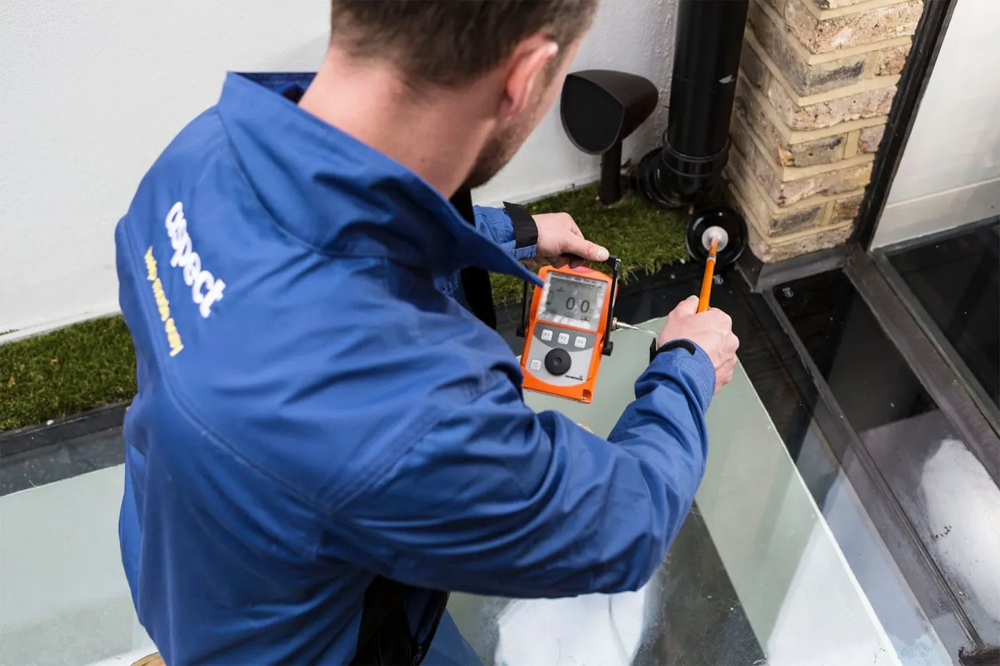
Leak detection is not one technique. It is a sequence: prove there is a leak, work out which system it is on, then use the method that suits the pipe, the floor and the failure. Here is how each method works and what defeats it.
What leak detection actually is
Leak detection is the process of establishing that water is escaping from a pressurised or draining system, working out which system, and locating the escape point precisely enough that someone can open one small area and find it. Each stage is a separate piece of work and they fail in different ways.
What people usually mean by leak detection is only the third stage, the locating. In practice the first two matter more, because a survey that goes straight to locating on the wrong system finds nothing and still takes three hours. A damp patch on a kitchen ceiling can come from a bath waste, a shower tray, a heating pipe, a supply pipe, a soil stack, a roof or condensation, and those are six different investigations.
It is also not damp diagnosis. A wall can be wet because a pipe is leaking, because water is coming in from outside, because a bridged damp proof course is drawing moisture up, or because a room produces more water vapour than it can ventilate. The instruments overlap but the reasoning does not, and our guide on telling damp and a leak apart deals with that distinction.
Before any instrument: proving the leak exists
Every competent survey starts by establishing that something is actually losing water, because a good proportion of call outs where the customer is certain there is a hidden leak turn out to be something else. Two cheap tests do most of that work.
The meter test
Close every tap and appliance, note the meter reading including the smallest dials, leave the property untouched, and read it again. Movement means water is going somewhere. Then close the internal stop tap and repeat: if the meter still moves, the loss is on the supply pipe between the meter and the stop tap, usually underground. If it stops, it is inside. That single step splits the job in two before anyone unpacks a case. Our guide to reading a water meter to check for a leak sets out how to do it and how to read the dials.
The pressure test
On internal pipework the equivalent is a static pressure test. The circuit is isolated, brought to a test pressure with a hand pump and a calibrated gauge, and watched. BS EN 806-4, which covers water supply systems inside buildings, describes a tightness test in which the system is filled with water, fully vented and held at 1.1 times the maximum design pressure with no drop permitted. The standard is explicit that the test uses water and not air, because compressed air in a pipe stores a dangerous amount of energy.
A heating circuit is tested the same way, and it is often the clearest result of the day. A sealed system that holds pressure overnight is not leaking, whatever anyone has been told, and one that drops steadily with the boiler isolated has narrowed the fault to the pipework rather than the appliance.
| Test | What it proves | What it cannot tell you |
|---|---|---|
| Meter reading with everything off | That a pressurised system is losing water | Which circuit, or where |
| Meter reading with the internal stop tap closed | Whether the loss is inside the building or on the buried supply pipe | Anything about waste, drainage or roof water |
| Circuit by circuit isolation | Which circuit the loss belongs to | The position of the defect along that circuit |
| Static pressure test to BS EN 806-4 | That a given circuit is or is not tight | The size or nature of the failure |
| Controlled water test of one fixture | Whether that fixture is the source | Anything about the fixtures you did not test |
Acoustic detection: listening to water escaping under pressure
Water forced through a small defect in a pressurised pipe makes noise. The turbulence at the orifice, and the impact of the jet on the surrounding material, produce vibration that travels along the pipe wall and through the ground or structure. Acoustic detection is the business of finding where that noise is loudest.
Two families of equipment do it. A ground microphone is a sensitive contact microphone placed on the floor surface, heavily filtered and amplified, moved in a grid while the operator listens for the peak. A correlator is different: two sensors are clamped to the pipe at accessible points either side of the suspected leak, and the instrument cross correlates the signals to find the time difference between the leak noise arriving at each. From the distance between the sensors and the speed of sound in that material, it computes the source position. That is why the operator must enter the pipe material, diameter and length accurately. It is the fastest method when conditions suit it, and usually the first thing tried on a pressurised pipe.
What acoustic detection cannot do
Acoustic methods need pressure and they need noise. Both of those can be absent.
- No pressure, no signal. A waste pipe, a soil stack, a shower tray, an overflow or a roof leak produces nothing useful, because nothing is being forced through a small hole.
- Plastic pipe is much quieter than metal. MDPE and barrier pipe damp vibration heavily, which shortens the distance the signal travels. Long plastic runs are the classic case where acoustic work narrows the area but does not pinpoint it.
- Very small and very large defects both go quiet. A slow weep may generate almost nothing. A catastrophic burst can drop pressure so far that the jet noise collapses.
- Deep pipes and loose ground absorb it. A pipe under a metre of soil is a much harder target than the same pipe under a concrete path.
- Background noise wrecks it. Traffic, a pump, a cistern refilling, the property's own boiler. Some of the hardest jobs in London are done at night because the street is quieter.
- Sound travels along the pipe. The loudest surface point is above the pipe, not necessarily above the defect, and on a run that changes depth the two can be some distance apart.
Our page on acoustic leak detection in London covers how this is applied in practice.
Thermal imaging: reading temperature, not water
A thermal camera does not see water and it does not see through anything. It measures infrared radiation emitted by a surface and converts it to an apparent temperature map of that surface. What makes it useful for leaks is that escaping water changes the temperature of the material it saturates, and that change eventually reaches a surface a camera can see.
That is why it is extremely effective on hot water and heating leaks and much weaker on cold ones. A leaking heating pipe under a screed produces a warm plume that spreads along the leak path and shows as a clear, shaped anomaly. A cold supply leak under the same screed produces a small temperature depression, sometimes a fraction of a degree, sometimes none at all once the water has equalised with the slab.
The technique has a formal basis. BS EN 13187 set out the qualitative infrared method for detecting thermal irregularities in building envelopes, and has been superseded by BS EN ISO 6781-1. The point those standards make is that thermography is qualitative. It identifies anomalies for investigation. It does not tell you what the anomaly is.
What thermal imaging cannot do
- It cannot see through a wall or a floor. It reads the surface. If the construction is thick, insulated or has an air gap, the anomaly may never reach the surface.
- It needs a temperature difference. A cold leak in a cold void in a cold house gives nothing. Sometimes the answer is to run the hot circuit and image again.
- Reflective and low emissivity surfaces lie. Gloss paint, tiles, polished stone, foil backed board and glass reflect infrared from elsewhere in the room, including the operator.
- Underfloor heating dominates everything. On a heated floor the loops are the only thing the camera wants to show you, and a leak has to be read against that pattern.
- It cannot distinguish sources. A cold patch can be a leak, condensation, a cold bridge, missing insulation or an air path. That judgement comes from a moisture meter and the building.
- Recent sun, radiators and occupancy contaminate the image. A wall that has had sun on it is unusable until it settles.
More on how it is used in practice is on our thermal imaging leak detection page.
Tracer gas: making an invisible leak detectable
When a leak is too small, too quiet or too cold for the other methods, the answer is to give it something detectable to emit. The system is drained, isolated and charged with a tracer gas, typically five per cent hydrogen in nitrogen, which is non toxic and, at that concentration, non flammable. Hydrogen is the smallest molecule there is, so it escapes through defects water barely weeps from, and it is far lighter than air, so it rises through screed, soil and floor construction to the surface where a sensitive detector picks it up. It is the most definitive method for a small leak in a buried pressurised pipe, and the one that closes jobs the other two only narrow.
What tracer gas cannot do
It is slow. The system has to be drained, which on a heating circuit means refilling, re dosing inhibitor and bleeding afterwards. The gas then has to reach the surface, which through a thick screed with a sealed floor finish can take a long time or not happen at all. A fully bonded vinyl or resin floor, or a membrane, can hold the gas beneath it, and the detector then reads a seam or a service penetration rather than the leak. It is also unusable on anything that cannot be sealed and pressurised, which rules out open waste systems and roofs. Our tracer gas leak detection page explains the preparation it requires.
Moisture measurement, hygrometry and cameras
The methods above find the pipe. These find the water, a different problem and frequently the one that decides what happens next.
| Instrument | What it physically measures | What it is good for | Where it misleads |
|---|---|---|---|
| Pin type resistance meter | Electrical resistance between two pins in the material | Comparative wetness readings in timber and plaster | Salts, foil, metal mesh and carbon all read as wet |
| Non invasive capacitance meter | Dielectric change a short distance below the surface | Quick surveying of a large area without damage | Reads pipes, wires and dense material as moisture |
| Endoscope or borescope | Direct visual access through a small hole | Confirming a suspicion before opening anything up | Only sees what the hole points at |
| Drain camera | Video inside a waste or soil pipe | Cracks, displaced joints, root ingress, blockages | Cannot show what is happening outside the pipe wall |
| Dye testing on drainage | Whether water from a fixture reaches a specific point | Proving a shower tray, waste or gully is the source | A negative result only rules out that one fixture |
Moisture mapping is what turns a located leak into a scope of works. Knowing the leak is at a particular joint is useful. Knowing how far the saturation extends into the floor void is what determines whether the room needs drying, and PAS 64, the code of practice for mitigation and recovery of water damaged buildings, is built around measuring and recording that rather than estimating it.
Matching the method to the symptom
Nobody chooses a method in the abstract. They choose it from what the property is doing.
| Symptom | Likely systems | Usual first method | Usual confirming method |
|---|---|---|---|
| Meter turns with the internal stop tap closed | Underground supply pipe | Acoustic, ground microphone and correlator | Tracer gas on a drained, capped supply |
| Warm patch on a solid floor | Heating flow or return, hot water | Thermal imaging | Pressure test on the isolated circuit |
| Boiler pressure falling, nothing visible | Heating circuit, or a discharging relief valve | Pressure test with the boiler isolated | Thermal imaging, then tracer gas |
| Stain on a ceiling under a bathroom | Waste, shower tray, seal failure, supply | Controlled water testing of each fixture in turn | Moisture mapping and endoscopy |
| Damp wall at low level, no meter movement | Possibly not a leak at all | Moisture profile and hygrometry | External inspection, drainage and gully checks |
| Wet patch in a garden or drive | Supply pipe, or drainage | Acoustic on the supply, dye on the drainage | Tracer gas on the supply pipe |
The methods work together, not in competition
The common misconception is that these are alternatives and a good engineer picks the right one. They are stages. Acoustic narrows a supply pipe leak from forty metres to two. Thermal confirms the anomaly behaves like water rather than a void. Tracer gas resolves the last half metre through a slab. Moisture mapping defines how far the damage has travelled. A survey producing a single point from a single instrument, with nothing corroborating it, is one to ask questions about, because the cost of being wrong is a floor opened in the wrong place. How this runs as a job is set out in our article on what a leak detection survey involves.
What a properly done detection leaves behind
The output of leak detection is not a hole in a floor. It is a decision someone can act on, documented well enough that a plumber, a loss adjuster and a managing agent can all use the same piece of paper.
- Which system is leaking. Named specifically: cold supply, hot supply, heating flow, heating return, waste, soil or external drainage.
- Where, with a reference someone else can find. Measured from two fixed features, not described as "under the hall".
- How it was established. The methods used and the ones tried that gave nothing, because that stops the next person repeating them.
- The confidence level. Whether the point is pinpointed or narrowed to an area, and what would close the gap.
- The extent of the damage. Moisture readings and the affected area, separately from the leak location.
- What access is required. What has to be opened, and anything that stops it, such as a screeded floor, a neighbour's ceiling or suspected asbestos in a building predating 2000.
Detection is a process of elimination carried out with instruments that each read one physical property, none of which is water in a pipe. Knowing what each is actually measuring, and what it cannot measure, is the whole skill.
How we help with this
If the article describes a problem you actually have, these are the visits that deal with it.
- our full guide to leak detection
How each method works and when it is the wrong tool for the job.
- leak detection in London
Finding a hidden leak without opening the property up first.
Frequently asked questions
What is leak detection?
Leak detection is the process of proving that a system is losing water, identifying which system it is, and locating the escape point precisely enough that one small area can be opened to reach it. It is not a single technique. A survey normally starts with a meter test and a pressure test to establish that a leak exists at all, then applies acoustic, thermal, tracer gas or moisture methods according to the pipe material, the construction and whether the water is hot or cold.
How do engineers detect leaks without damaging the property?
By reading physical effects at the surface rather than opening the structure. Acoustic equipment picks up the vibration made by water escaping from a pressurised pipe. Thermal cameras read temperature anomalies at a surface where escaping water has changed the material behind it. Tracer gas, usually five per cent hydrogen in nitrogen, is put into a drained pipe and detected where it surfaces. Moisture meters and endoscopes then confirm the finding before anything is cut.
Which leak detection method is the most accurate?
None of them is most accurate in general, because each reads a different physical property and each is defeated by different conditions. Tracer gas is usually the most definitive on a small leak in a buried pressurised pipe, but it needs the system drained and a path to the surface. Acoustic is fastest on metal supply pipe under pressure and weak on plastic and waste. Thermal is strong on hot water and heating and often blind to cold leaks. Real surveys combine them.
Can a thermal camera see a water leak through a wall?
No. A thermal camera measures infrared radiation emitted by a surface and converts it to an apparent temperature map of that surface. It cannot see through anything. It works for leaks only where escaping water has changed the temperature of the material enough for that change to reach the surface. Standards for infrared building surveys, BS EN 13187 and its successor BS EN ISO 6781-1, describe it as a qualitative method that identifies anomalies for investigation rather than identifying their cause.
Why does a leak detection survey start with a pressure test?
Because it answers the most important question cheaply. BS EN 806-4 describes a tightness test in which a water installation is filled, vented and held at a test pressure with no drop permitted. A circuit that holds pressure is not leaking, whatever the symptoms suggest, and a circuit that drops has narrowed the fault to that pipework rather than an appliance. Doing this first stops hours being spent with instruments on a system that turns out to be sound.
What can leak detection not find?
Anything that is not a leak, and several things that are. Acoustic methods need pressure, so waste pipes, soil stacks, shower trays, overflows and roofs give no useful signal. Thermal needs a temperature difference, so a cold leak in a cold void can be invisible. Tracer gas needs a sealed system and a path to the surface, so a fully sealed floor finish can trap it. And damp caused by condensation, penetrating water or a bridged damp proof course is a separate diagnosis entirely.